BDI: 1,842 ▼ 1.2%
COTTON NO.2: 84.12 ▲ 0.4%
LME COPPER: 8,432.50 ▲ 2.1%
FOOD SAFETY INDEX: 94.2 ARCHIVE_SECURED
OPTICAL INDEX: 11,204.09 STABLE
BDI: 1,842 ▼ 1.2%

SECTOR INDEX
V.24.08 ARCHIVE
Hot Articles
- When Is a Straddle Monorail System a Good Fit for Urban Transit Corridors?Is a straddle monorail system right for your urban corridor? Explore capacity, space, station access, safety, and lifecycle costs to make a confident transit investment.
- EU Textile Waste Reporting: Who Must Report and What Data Is Required?EU textile waste reporting explained: discover who must report, what data is required, and how to verify EPR, waste records, and shipment compliance across EU markets.
- Yarn Strength Benchmarks for Weaving: Setting Warp and Weft RequirementsSet yarn strength benchmarks for weaving with practical warp and weft criteria. Learn how tenacity, variability, and loom loads inform specifications that help reduce breaks and improve reliability.
Rail Signal Visibility: Sighting Distance, Contrast, and Verification Requirements


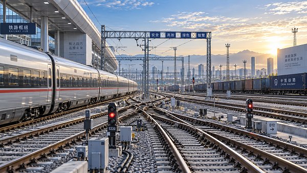
Rail signal visibility is not established by lamp output or a nominal viewing distance alone. A signal is safe to use only when the intended driver can detect it, recognize it as the applicable signal, read the displayed indication correctly, and do so early enough to respond within the available braking and operating margin. This is why rail signal visibility must be controlled as a route-specific safety function rather than treated as a component-level acceptance check.
For quality and safety control, the central question is not “can the signal be seen?” but “can the correct indication be reliably perceived at the required decision point under the conditions permitted for operation?” The difference is material. A signal may appear conspicuous during a daytime inspection from track level yet provide inadequate recognition time from a cab at line speed, be confused with adjacent lighting at night, or lose contrast against a changing background after vegetation growth or infrastructure modification.
Visibility is a chain of detection, recognition, and response
Signal sighting requirements generally combine three linked conditions:
- Detection: the driver notices that a signal is present in the visual field.
- Recognition: the driver identifies the correct signal and distinguishes its aspect, route indicator, or associated sign from other lights and trackside objects.
- Response: the driver has sufficient distance and time to interpret the indication, apply the relevant rule, and bring the train under control where required.
A bright signal can support detection without guaranteeing recognition. Likewise, a signal that is geometrically visible may still be operationally deficient if the driver encounters it after the braking decision point. Sighting distance therefore has to be related to train speed, gradient, braking characteristics, route knowledge assumptions, reaction time specified by the railway administration, and the operational consequence of the most restrictive aspect.
The applicable rulebook and infrastructure standard determine the exact calculation method. These requirements vary by jurisdiction and railway system. In Europe, signal visibility sits within a broader safety and interoperability framework, while national infrastructure managers define detailed sighting, positioning, maintenance, and approval arrangements. In the United States, Federal Railroad Administration requirements under 49 CFR Part 236 address signal-system safety, alongside railroad-specific engineering standards and operating rules. No single international standard provides a universal sighting-distance figure that can be transferred unchanged between networks.
The important control principle is consistent: the required distance must be justified against the route’s operating risk, not selected as a convenient round number.
Sighting distance must be measured from the driver’s real approach
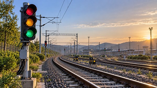
Distances taken from a track plan, a signal location drawing, or a handheld measurement at the base of the mast are not sufficient evidence by themselves. The relevant line of sight begins at the driver’s viewing position and follows the actual approach path. Horizontal curvature, vertical curves, cant, cab height, track divergence, platform structures, tunnel portals, overhead line equipment, and the position of other trains can all alter what is visible from the cab.
Vertical geometry is frequently underestimated. A signal can be physically unobstructed on a plan view but remain hidden until late in the approach because of a crest curve, a bridge soffit, or a raised platform canopy. Conversely, a downhill approach may create an apparently long view while reducing braking margin. The sighting assessment must therefore link physical visibility to the point at which a driver must make an operational decision.
Where a route has multiple possible paths, the correct signal must remain unambiguous for each permitted movement. This becomes more demanding at junctions, station throats, depots, bidirectional sections, and locations with parallel lines. The assessment should establish whether adjacent signals can be mistaken for the governing signal, particularly when signals are mounted at different lateral offsets or when several signal heads enter the driver’s field of vision at once.
Line speed is only one input. The safety significance of a restrictive indication also matters. A distant warning, a stop indication, a speed restriction, a route indication, or a movement authority transition may each require a different recognition point. Where automatic train protection, cab signalling, or in-cab displays provide a separate layer of control, the visual signal’s role must still be defined clearly. The presence of an in-cab system does not automatically remove the need to maintain safe and intelligible external indications unless the operating system and applicable rules explicitly permit that dependency.
Contrast determines whether an aspect can be interpreted correctly
Signal luminance is often discussed as though higher output automatically creates better visibility. In practice, visibility depends on contrast: the relationship between the illuminated aspect and its immediate and wider background. A signal viewed against a dark cutting face, bright sky, reflective building, low sun, station lighting, or illuminated advertising can perform very differently even when the signal head itself has not changed.
Daytime and nighttime conditions create different risks. In strong daylight, a low-intensity aspect may be difficult to detect against bright sky or sunlit surfaces. At night, excessive intensity can cause glare, bloom, colour washout, or confusion with road traffic lights, platform lighting, worksite lamps, and building lights. LED signal heads offer useful advantages in consistency, power consumption, and monitoring capability, but they do not eliminate contrast management. Their narrow optical distribution, colour performance, perceived intensity, and compatibility with existing lens or hood arrangements must be assessed within the installed environment.
Colour discrimination deserves separate attention. Drivers must be able not only to see light, but to distinguish the intended colour and any associated marker or route display. This can be affected by lens contamination, ageing, optical misalignment, non-compliant replacement parts, reflections within the signal housing, and the colour of nearby artificial lights. A maintenance record showing that an LED module is energized is not proof that the displayed aspect remains compliant or legible from the required viewing zone.
Background change is a recurring source of latent non-conformity. Seasonal foliage can obstruct or visually merge with a signal. New buildings, acoustic barriers, gantries, utility cabinets, road schemes, solar installations, platform screens, or commercial lighting can degrade conspicuity after the original design has been approved. Even a newly painted structure can alter the local contrast enough to justify reassessment. Visibility control must therefore include change management, not only periodic lamp inspection.
Weather is a performance condition, not an exception to ignore
Fog, heavy rain, snow, blowing dust, spray, low-angle sunlight, and windscreen contamination can reduce the practical range at which an indication is recognized. A railway cannot normally design a lineside signal to remain fully effective in every extreme weather condition; operating rules may impose speed restrictions or other controls when visibility is severely reduced. Nevertheless, normal seasonal weather exposure should be reflected in sighting decisions and verification planning.
Rain can create reflections on rails, platform surfaces, and adjacent structures. Snow may mask signal posts, boards, or low-mounted equipment. Low sun can generate glare directly ahead of the driver or produce shadow transitions that delay detection. These factors are especially relevant where a signal is positioned near a road crossing, water surface, glazed facade, or station lighting installation.
A sound verification regime distinguishes between conditions that are controlled through design and maintenance and conditions that trigger operational mitigation. Treating all adverse visibility as unavoidable weather risk can conceal correctable defects such as poorly oriented heads, inadequate hoods, degraded lenses, unmanaged vegetation, or distracting local lighting.
Verification must produce defensible evidence
Signal sighting is often approved at commissioning, but approval alone does not demonstrate continued compliance throughout the asset life. A robust verification process should create evidence that can be reviewed after an incident, audit, route modification, or maintenance dispute. The evidence needs to show what was checked, from where, under what conditions, using which acceptance criteria, and what corrective action followed where a deficiency was found.
Cab-based observation is particularly valuable because it reflects the driver’s actual perspective. Depending on the infrastructure manager’s procedures, verification may use a controlled train movement, a cab simulation based on validated geometry, video capture from an appropriate viewing position, or a combination of these methods. Static ground-level photographs are useful supporting records, but they can distort perspective and do not substitute for a route-representative assessment.
Records should identify the signal asset, direction of travel, track or route concerned, aspect or indication assessed, viewing distance or chainage, line speed, relevant braking or decision point, foreground and background conditions, obstructions, and the status of adjacent signals. Where digital images or video are retained, the file should be traceable to the inspection date and asset reference. Evidence without location control or without a stated acceptance basis has limited audit value.
Instrumented photometric testing may be necessary when visual performance is disputed, when LED conversions are introduced, or where signal intensity and colour performance are subject to defined technical limits. Such testing should use calibrated equipment and controlled procedures appropriate to the signal technology. It should not be confused with a complete sighting assessment: photometric conformity verifies an important property of the signal unit, while sighting verifies the installed safety function.
Maintenance inspections should separate asset defects from route defects
Many visibility failures do not originate inside the signal head. A useful inspection discipline separates defects into two categories.
Asset-related defects include failed lamps or LED modules, dirty or damaged lenses, moisture ingress, faded filters, damaged hoods, loose alignment, incorrect mounting, degraded route indicators, and wiring faults that affect aspect display. These issues are normally addressed through signal maintenance controls, replacement-part assurance, functional testing, and post-repair verification.
Route-related defects include vegetation, new structures, signs, temporary works, parked rolling stock, cranes, scaffolding, lighting spill, changed track geometry, platform alterations, and overhead line changes. These require coordination across civil engineering, operations, property management, construction control, and asset maintenance. They are easy to miss when inspection responsibilities are divided by discipline.
Temporary conditions require the same seriousness as permanent works. Construction hoardings, portable lighting towers, possession equipment, and altered train stabling arrangements can obscure or confuse a signal for a limited period, yet the operational consequence exists immediately. Work planning should include a formal review of signal visibility whenever a temporary installation enters the signal’s approach envelope or visual background.
Common assurance failures
One common error is accepting a signal because it is visible at the moment it first appears, without confirming whether its indication can be read and acted upon in time. Another is relying on a clear-weather daytime inspection to close a concern involving night glare or low-sun conditions. A third is treating vegetation clearance as a purely aesthetic task rather than defining a controlled sightline envelope that must remain free of obstruction.
There is also a governance failure: changes to nearby assets are approved independently, while no one is assigned to reassess the signal’s visual environment. Effective configuration management should identify signal sighting as a protected interface. Any project that changes structures, lighting, track alignment, platform arrangements, or overhead equipment within the relevant visual corridor should trigger review by the competent signalling and operational authorities.
Where a deficiency is identified, the response should match the risk and the time needed for permanent correction. Possible measures can include vegetation removal, signal realignment, improved screening or hooding, background treatment, relocation, repeater provision, revised lighting arrangements, temporary speed control, or operational instructions. A short-term mitigation should have a clear owner, validity period, and closure condition; otherwise it can become an undocumented substitute for design correction.
Compliance depends on a controlled lifecycle
Rail signal visibility is sustained through design approval, installation verification, routine inspection, maintenance, change control, and documented revalidation. The most reliable programmes treat the signal, the driver’s approach, the surrounding environment, and the operating rule as one controlled system.
That approach avoids a narrow focus on whether a lamp illuminates. It asks whether the intended indication remains unmistakable at the point where it matters, under the route conditions that the railway has accepted for operation. For safety assurance, that is the standard that makes sighting distance, contrast, and verification records meaningful.
Recommended for You
 Digital SeaWhen Is a Straddle Monorail System a Good Fit for Urban Transit Corridors?Is a straddle monorail system right for your urban corridor? Explore capacity, space, station access, safety, and lifecycle costs to make a confident transit investment.By: Captain Kenji SatoOct 19, 2026
 Fabric LogicEU Textile Waste Reporting: Who Must Report and What Data Is Required?EU textile waste reporting explained: discover who must report, what data is required, and how to verify EPR, waste records, and shipment compliance across EU markets.By: Chloe DuboisOct 18, 2026
 Fabric LogicYarn Strength Benchmarks for Weaving: Setting Warp and Weft RequirementsSet yarn strength benchmarks for weaving with practical warp and weft criteria. Learn how tenacity, variability, and loom loads inform specifications that help reduce breaks and improve reliability.By: Chloe DuboisOct 17, 2026
 Fabric LogicEnergy-Saving Textile Machinery: How to Calculate Payback for Your MillEvaluate energy saving textile machinery with a practical payback formula, real-world cost factors, and a worked example. Discover how to verify savings and invest confidently in your mill.By: Chloe DuboisOct 16, 2026
 Digital SeaETSC Adoption in Europe: Policy Drivers, Costs, and Implementation BarriersExplore ETSC adoption Europe-wide: uncover policy drivers, installed costs, and implementation barriers to evaluate solar thermal investments and identify projects with stronger returns.By: Captain Kenji SatoOct 15, 2026
 Digital SeaChoosing Semiconductor Solutions for Industrial Controls: Key Design CriteriaChoose semiconductor solutions for industrial controls with confidence. Explore key criteria for timing, accuracy, power, safety, and lifecycle support to make smarter design decisions.By: Captain Kenji SatoOct 14, 2026
 Aseptic FillingWhen Should Compliance Checks Start for Aseptic Filling Procurement?How early should compliance checks start in procurement planning? Learn why aseptic filling reviews should begin before supplier shortlisting to reduce risks, rework, and costly delays.By: Marcus SterlingOct 13, 2026
 Smart MetersHow Do You Assess Market Demand Before Sourcing New Smart Meters?How do I assess market demand before sourcing a new industrial product? Discover how to validate smart meter demand, check technical fit, and reduce inventory risk before committing to bulk orders.By: Dr. Elena VoltOct 13, 2026
 GIS SwitchgearWhat Should You Compare Besides Price When Selecting GIS Switchgear?What should I compare besides price when selecting an industrial product? Explore GIS switchgear ratings, IEC compliance, maintenance and lifecycle costs to make a confident procurement decision.By: Dr. Elena VoltOct 13, 2026
 Optical SensorsHow Do You Choose Optical Sensors for Harsh Industrial Environments?How do I choose components for harsh industrial environments? Discover how to select optical sensors for dust, heat, vibration, and washdown—and prevent costly missed detections.By: Dr. Hideo TanakaOct 13, 2026
 Marine WinchesWhich Operating Conditions Can Change Marine Winch Selection?Which industrial application conditions can change product selection? Explore how loads, sea state, duty cycle and power shape marine winch selection to make a smarter investment.By: Captain Kenji SatoOct 13, 2026
 Digital SeaChoosing a Seismic Survey Equipment Distributor: Lead Times and Spare PartsChoosing a seismic survey equipment distributor? Learn how to verify lead times, secure critical spare parts, and compare support to reduce downtime and buy with confidence.By: Captain Kenji SatoOct 13, 2026
 Digital SeaHow to Use Industrial Benchmarking Data to Evaluate Supplier Risk and CapabilityIndustrial benchmarking data for supplier evaluation helps buyers assess capability, compliance, capacity, and delivery risk. Learn how to make smarter, evidence-based sourcing decisions.By: Captain Kenji SatoOct 12, 2026
 Fabric LogicFashion Supply Chain Cost Trends: What Is Driving Margins in 2026?Fashion supply chain cost trends for 2026: discover how materials, freight, labor, compliance, and inventory are reshaping margins—and the strategies leaders need to protect profitability.By: Chloe DuboisOct 11, 2026
 Lumen VisionHow Smart Street Lighting Cuts Energy Use Without Compromising Road SafetySmart street lighting reduces energy use while protecting road safety through adaptive controls, reliable monitoring, and risk-based lighting design. Learn the key strategies.By: Dr. Hideo TanakaOct 10, 2026
 Digital SeaDouble Platinum Spark Plugs: When Their Longer Service Life Justifies the CostDouble platinum spark plugs offer longer service life, stable gaps, and lower labor costs. Learn when their premium price is worth it for your vehicle.By: Captain Kenji SatoOct 08, 2026
 Sorting RobotsHow to Benchmark Linear Guide Load Ratings for High-Cycle Automation AxesLinear guide load rating benchmarks for high-cycle automation axes: compare loads, moments, stiffness, lubrication, and life calculations to select reliable guides.By: Marcus SterlingOct 07, 2026
 Digital SeaWhich Rail Data Transparency Metrics Improve Capacity Planning and Service Reliability?Rail data transparency metrics reveal usable capacity, dwell, recovery, and asset risks—helping rail leaders plan more reliable, resilient services.By: Captain Kenji SatoOct 06, 2026
 Digital SeaHow to Select a Marine Piston Air Compressor for High-Demand Shipboard ServiceMarine piston air compressor selection guide for high-demand shipboard service—compare capacity, redundancy, air quality, maintenance, and compliance requirements.By: Captain Kenji SatoOct 05, 2026
 Grid ResilienceIEC 61850 Monitoring Latency: How to Set Performance Limits for Protection SystemsIEC 61850 monitoring latency explained: learn how to set, test, and verify end-to-end performance limits that protect critical GOOSE and Sampled Values systems.By: Dr. Elena VoltOct 04, 2026
 Digital SeaHow to Select Bulldozers by Blade Type, Ground Conditions, and Earthmoving OutputBulldozers selection made practical: compare blade types, track setups, ground conditions, and cycle output to choose the right dozer for lower costs and reliable earthmoving.By: Captain Kenji SatoOct 03, 2026
 Dyeing MachinesHow Sustainable Dyeing Cuts Water Use and Chemical Risk in Textile ProductionSustainable dyeing cuts water use and chemical risk through smarter liquor control, efficient rinsing, safer inputs, and repeatable textile quality.By: Chloe DuboisOct 02, 2026
 Optical SensorsSingle-Mode Fiber Loss in Railway Networks: Causes, Budgets, and Test MethodsSingle mode railway fiber loss explained: identify causes, calculate realistic loss budgets, and apply OTDR and insertion-loss tests for reliable rail networks.By: Dr. Hideo TanakaOct 01, 2026
 Digital SeaIntegrated Transit Hub Planning: How to Balance Passenger Flow and Future CapacityIntegrated transit hub planning strategies for balancing passenger flow, resilient operations, phased delivery, and future capacity—explore practical insights for smarter hubs.By: Captain Kenji SatoSep 30, 2026
 Digital SeaWhat to Evaluate When Selecting a MaaS Ticketing Platform for Multimodal NetworksMaaS ticketing platform selection guide: evaluate interoperability, fare control, settlement, resilience, privacy, and scalability for multimodal networks.By: Captain Kenji SatoSep 29, 2026
 Digital SeaWhat Does Train Control Center Software Cost? Budgeting for Integration and SupportTrain control center software cost explained: compare integration, cybersecurity, commissioning, and long-term support to build a realistic rail operations budget.By: Captain Kenji SatoSep 28, 2026
 Digital SeaWhat to Evaluate in Thermite Rail Welding Equipment for Field Track RepairsThermite rail welding equipment: evaluate compatibility, preheating, alignment, safety, and supplier support for reliable field track repairs.By: Captain Kenji SatoSep 27, 2026
 Aseptic FillingISO 22000 Food Safety Certification: What Food Manufacturers Must PrepareISO 22000 food safety certification: discover the essential steps manufacturers need to build a robust FSMS, control hazards, and prepare confidently for audit success.By: Marcus SterlingSep 26, 2026
 UHV TransformersWhat Makes an Electrification Factory Ready for High-Voltage Equipment Production?Electrification factory readiness for high-voltage equipment: discover the essential standards, testing, traceability, safety, and workforce controls that drive reliable production.By: Dr. Elena VoltSep 25, 2026
 Digital SeaRail Signal Visibility: Sighting Distance, Contrast, and Verification RequirementsRail signal visibility: learn how sighting distance, contrast, weather, and verification controls help ensure safe, compliant signal recognition.By: Captain Kenji SatoSep 24, 2026
![]() GIS SwitchgearHow Do You Compare GIS Switchgear Suppliers When Certifications Differ?How do I compare industrial suppliers when certifications are not equivalent? Learn how to assess GIS switchgear test evidence, compliance scope, traceability, and project risk.By: Dr. Elena VoltSep 24, 2026