BDI: 1,842 ▼ 1.2%
COTTON NO.2: 84.12 ▲ 0.4%
LME COPPER: 8,432.50 ▲ 2.1%
FOOD SAFETY INDEX: 94.2 ARCHIVE_SECURED
OPTICAL INDEX: 11,204.09 STABLE
BDI: 1,842 ▼ 1.2%

SECTOR INDEX
V.24.08 ARCHIVE
Hot Articles
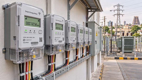
- Tamil Nadu Plans SIM-Based Upgrade for 17.7 Million Smart MetersTamil Nadu plans 17.7 million smart meters with proposed SIM-based upgrades. Explore potential supplier opportunities and the tender details still to come.
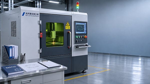
- Fiber Laser CE Marking: EU Safety Requirements and DocumentationFiber laser CE compliance goes beyond the mark. Explore EU safety requirements, essential documentation and practical checks before purchasing.
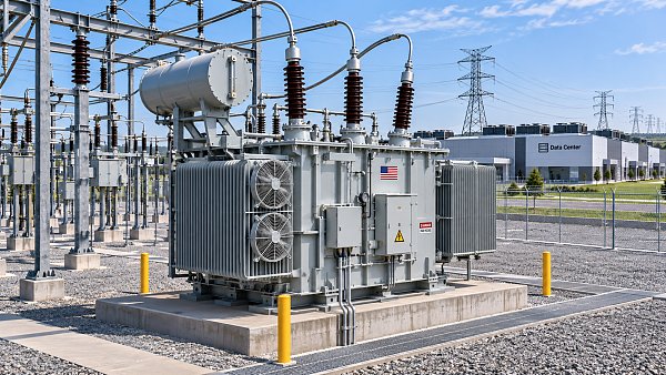
- US Grid Equipment Shortages Could Hinder $1 Trillion UpgradeUS grid equipment shortages could hinder a $1 trillion upgrade. Explore how transformer supply, data centers and rising power demand could affect grid projects.
How Are Fiber Lasers Used in Industrial Manufacturing?


Fiber lasers cut sheet metal, weld components, mark parts, and remove selected surface layers by concentrating optical energy into a controlled spot. Their industrial value comes from combining localized heating with programmable motion: the same process can follow complex contours, join small features, or reproduce identification marks across a production run. Results depend on how the beam interacts with the material, how the workpiece is positioned, and how heat and debris are managed.
A machine configured for cutting steel plate is fundamentally different from one designed to mark electronic housings. Average power alone does not establish suitability. Wavelength, pulse duration, beam profile, focusing optics, motion control, and process monitoring determine whether the laser produces an acceptable part at the required production rate.
Match the laser configuration to the manufacturing task
In a fiber laser, the active gain medium is an optical fiber doped with rare-earth elements. Many industrial metalworking systems use ytterbium-based sources operating in the near-infrared region. The beam is delivered to a processing head, where optics focus or shape it for a particular operation.
Continuous-wave sources deliver sustained energy and are widely used for cutting and welding. Pulsed sources concentrate energy into timed bursts, supporting marking, engraving, cleaning, and certain micromachining operations. Shorter pulses can limit heat diffusion during material removal, although the result also depends on pulse energy, repetition rate, and how successive pulses overlap.
These categories are starting points. A pulsed marking source does not become a suitable welding source simply because its peak power is high. Likewise, a tightly focused beam that cuts efficiently can create an unstable weld if the joint requires a wider, more forgiving heat distribution.
Sheet-metal cutting: the edge determines the useful speed
During laser cutting, the focused beam heats material along a programmed path while assist gas clears molten material from the kerf. This enables detailed contours, holes, and nested parts without a dedicated cutting tool for each shape. Common applications include machine enclosures, electrical cabinets, brackets, and fabricated assemblies.
Material thickness changes the process balance. Thin sheet supports rapid motion, but acceleration and corner handling can dominate the cycle time on intricate parts. Thicker material requires stable penetration and effective melt removal. Increasing source power cannot compensate indefinitely for an unsuitable nozzle, incorrect focus, or poor gas delivery.
Assist-gas selection also changes the finished edge. Oxygen supports a reactive cutting process in carbon steel and leaves an oxidized edge. Nitrogen is used where an oxide-free edge is needed, provided gas purity and process conditions are suitable. The choice affects downstream welding, coating preparation, gas consumption, and overall production cost.
Cut quality needs inspection beyond the top surface. Dross underneath the sheet, edge taper, corner overheating, and inconsistent small holes can create deburring or assembly work. A representative cutting trial should include tight contours and repeated pierces, since long straight cuts alone give an incomplete picture of usable throughput.
Reflective metals introduce additional demands. Copper and aluminum require a source and optical system designed for the interaction, including protection against damaging back-reflections. Material condition matters too: coatings, surface contamination, and alloy differences can change piercing behavior and edge consistency.
Welding battery connections, housings, and precision assemblies
Fiber laser welding concentrates heat around a joint, allowing narrow seams and controlled access to small features. Applications include battery interconnects, sensor housings, automotive components, and sealed metal assemblies. The process supports automation when joint location, fit-up, and surface condition remain consistent.
Two welding modes help explain the tradeoffs. Conduction welding forms a relatively shallow melt pool without a sustained vapor cavity. Keyhole welding uses higher power density to establish a vapor cavity and achieve deeper penetration. An unstable keyhole can produce porosity or spatter, so deeper penetration does not automatically indicate a better joint.
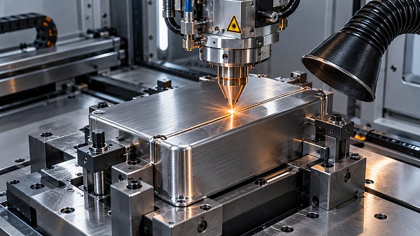
Joint gaps are especially important because a narrow beam offers limited ability to bridge missing material. Accurate fixtures and consistent edge preparation help maintain contact. Beam oscillation can distribute energy over a wider area and improve tolerance to some joint variation, but it also changes heat input and requires validation for the actual seam geometry.
Battery connections illustrate why material-specific testing matters. Copper conducts heat away quickly and initially absorbs near-infrared light poorly. Thin tabs also provide little margin between insufficient fusion and excessive penetration. Surface preparation, beam shaping, temporal power control, and alternative wavelengths deserve evaluation when a conventional configuration produces inconsistent results.
Dissimilar-metal joints add metallurgical constraints. A visually smooth copper-to-aluminum weld can contain brittle intermetallic regions or have inadequate electrical performance. Qualification therefore needs evidence relevant to the connection, such as cross-sections, mechanical testing, electrical resistance, and thermal behavior under the intended load. Appearance alone cannot establish joint reliability.
Permanent marking and traceability on electronic parts
Pulsed fiber lasers mark serial numbers, data codes, logos, and functional identifiers on metal parts. The visible result can come from material removal, controlled surface oxidation, or modification of a coating. These mechanisms create different combinations of contrast, depth, texture, and resistance to subsequent processing.
Engraving removes material and produces a recessed mark. On suitable stainless steels, controlled heating can create an oxide-based mark with little material removal. Coated components offer another route: removing a top layer exposes a contrasting substrate. Selecting the mechanism requires considering both readability and the component’s surface requirements.
Electronic housings and connectors often have limited marking space. Scanner accuracy, lens selection, focus height, and part location influence whether a small code remains readable. A mark that looks dark to the eye can still perform poorly under machine vision because of glare, roughness, cell distortion, or inconsistent lighting.
The full production sequence matters. Cleaning, abrasion, coating, and heat exposure can alter contrast after marking. Code verification should therefore reflect the condition in which the identifier will actually be read. Mark placement must also avoid sealing faces, electrical contacts, and regions where engraving could weaken a thin wall.
Polymer compatibility requires separate assessment. Many plastics do not respond well to the near-infrared output of common fiber lasers without suitable additives or formulations. Excessive heating causes melting, foaming, or charring. For heat-sensitive polymers and some electronic materials, another laser wavelength can provide a more suitable interaction.
Cleaning and selective removal require a process window
Pulsed fiber lasers remove rust, paint, oxides, or residues by delivering energy that detaches or ablates a surface layer. Applications include preparing weld areas, cleaning tooling, and exposing selected regions of coated parts. The absence of abrasive media is useful where media residue would interfere with later processing.
Successful cleaning relies on a usable separation between the conditions that remove contamination and those that damage the substrate. That separation changes with coating thickness, adhesion, substrate material, and surface geometry. A setting that cleans one region effectively can overheat an adjacent edge or alter a polished surface.
Removal also generates airborne particles and, for some coatings, hazardous decomposition products. Extraction must capture these emissions near the interaction point. Trials should evaluate the cleaned surface for its next operation: coating adhesion, weldability, surface roughness, or electrical contact performance. A bright appearance does not prove that residues have been removed.
Small features expose the limits of power-based comparisons
Fiber lasers also drill holes, trim features, and texture surfaces where the material and feature dimensions suit the source. Pulsed systems offer control over individual energy deposits, while scanning optics position the beam rapidly across a working field. These capabilities support selected tasks in precision components and electronic assemblies.
For fine features, pulse duration and spot size become particularly important. Excess heat can leave recast material, burrs, microcracks, or damage beneath the visible surface. Shorter pulses reduce thermal diffusion during each pulse, but heat can still accumulate when pulses arrive rapidly or scan paths repeatedly cross the same region.
Average power describes energy delivered over time; it does not describe how that energy is distributed. Two sources with similar average power can produce different outcomes because their pulse energies, pulse widths, and beam characteristics differ. Acceptance should focus on the finished feature, including dimensional variation and edge condition.
Production performance comes from the complete cell
A laser source is only one element of a manufacturing system. Fixtures, motion stages or robots, scanning heads, vision, extraction, cooling, controls, and material handling all affect output. Fast beam processing offers limited benefit when loading, alignment, or part transfer consumes most of the cycle.
Fixtures must hold the relevant geometry without obstructing the beam or trapping fumes. Welding fixtures also influence heat flow and distortion. For cutting, sheet support and removal procedures affect scratching, tip-up collisions, and the handling of small parts. These details often explain why a successful laboratory demonstration becomes inconsistent during production.
Focus control deserves particular attention. Part-height variation changes spot size and energy density at the surface. Height sensing, autofocus, or three-dimensional positioning can address relevant variation, but each adds requirements for calibration and control. Dirty protective windows create another source of drift by changing optical transmission and increasing local heating.
Monitoring provides useful signals when linked to verified outcomes. Back-reflected light, thermal emission, acoustic signals, or camera images can reveal process changes, yet a stable signal does not by itself prove weld integrity. Monitoring thresholds need correlation with destructive testing or other established inspection methods.
Laser containment is part of cell design. Near-infrared processing beams are invisible, and reflections can create exposure beyond the immediate work area. Enclosures, interlocks, suitable viewing arrangements, and extraction need to accommodate loading and maintenance without making normal production impractical.
Evidence that makes equipment comparisons meaningful
A useful acceptance trial uses representative material, realistic fixtures, and production-relevant geometry. Ideal flat coupons establish feasibility but rarely expose the full effect of part tolerances, coatings, thermal buildup, or handling variation. Trials should include the conditions expected across normal incoming material and an extended run long enough to reveal process drift.
Three forms of evidence make comparisons more useful:
- Defined part quality: measurable edge, seam, mark, or surface requirements, with inspection methods agreed before testing.
- Complete cycle time: loading, positioning, processing, inspection, and unloading measured together. Beam-on time alone understates the production burden.
- Operating requirements over sustained use: assist gas where applicable, extraction filters, protective optics, cooling, fixture maintenance, and service access. Their significance changes substantially between cutting, welding, and marking.
When evaluating electronics sourcing market opportunities, equipment and contract-processing offers become more comparable when they describe the actual part, acceptance limits, and production conditions. A quoted laser wattage or nominal marking speed leaves too much unresolved. A documented process window, supported by inspected samples and repeatable cycle data, establishes what the proposed system can deliver on the intended manufacturing task.
Recommended for You
 Smart MetersTamil Nadu Plans SIM-Based Upgrade for 17.7 Million Smart MetersTamil Nadu plans 17.7 million smart meters with proposed SIM-based upgrades. Explore potential supplier opportunities and the tender details still to come.By: Dr. Elena VoltNov 22, 2026
 Fiber LasersFiber Laser CE Marking: EU Safety Requirements and DocumentationFiber laser CE compliance goes beyond the mark. Explore EU safety requirements, essential documentation and practical checks before purchasing.By: Dr. Hideo TanakaNov 22, 2026
 Grid ResilienceUS Grid Equipment Shortages Could Hinder $1 Trillion UpgradeUS grid equipment shortages could hinder a $1 trillion upgrade. Explore how transformer supply, data centers and rising power demand could affect grid projects.By: Dr. Elena VoltNov 21, 2026
 Digital SeaChoosing Bluetooth Speakers: Sound Quality, Battery Life and PortabilityBluetooth speakers come in all shapes and sizes. Learn how to compare sound quality, battery life and portability to find the right fit for your listening needs.By: Captain Kenji SatoNov 21, 2026
 Subsea ROV/AUV2025 Ocean Equipment Report: China's Industry Moves Toward Scaled ApplicationChina's marine equipment industry is moving toward scaled application. Explore what the 2025 Ocean Equipment Report could mean for buyers, suppliers and offshore projects.By: Captain Kenji SatoNov 20, 2026
 Digital SeaChoosing a Thermoforming Vacuum Packaging Machine for Meat ProductsChoose a thermoforming vacuum packaging machine for meat with confidence. Compare sealing, film compatibility, hygiene and real-world production capacity.By: Captain Kenji SatoNov 20, 2026
 Digital SeaGreen Station Certification Cost: Fees and Budget ConsiderationsGreen station certification cost varies by scheme and site. Explore fees, hidden expenses, and budgeting tips to plan confidently and compare providers.By: Captain Kenji SatoNov 19, 2026
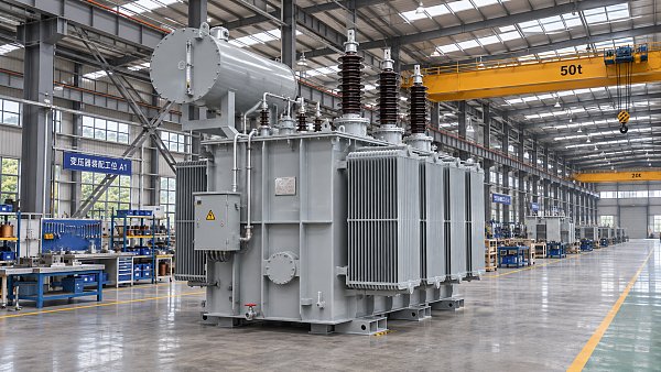
 UHV TransformersLIMiK Capital to Invest $328 Million in South Carolina Transformer PlantLIMiK Capital plans a $327.7 million transformer plant in South Carolina. Explore its potential impact on US grid supply and procurement.By: Dr. Elena VoltNov 18, 2026
 Digital SeaHow to Choose STEM Kits for Kids by Age, Interests, and Skill LevelChoose STEM kits that match your child's age, interests, and skills. Explore safety tips, project ideas, and practical checks to find an engaging fit.By: Captain Kenji SatoNov 18, 2026
 Digital SeaManufacturing Supplier Requirements: What to Include in Technical SpecificationsDiscover how manufacturing technical specifications and supplier requirements improve quality, simplify comparisons, and prevent delays with measurable acceptance criteria.By: Captain Kenji SatoNov 17, 2026
 Digital SeaChina's Environment Ministry Opens ALC Submarine Cable Project to ReviewChina's Environment Ministry opens the ALC submarine cable project's environmental assessment to review. Explore the proposed marine protection measures and what comes next.By: Captain Kenji SatoNov 16, 2026
 Precision LensesOptical Lens Surface Roughness Testing: Methods and Ra InterpretationOptical lens surface roughness testing explained: compare measurement methods, interpret Ra values, and define reliable acceptance criteria.By: Dr. Hideo TanakaNov 16, 2026
 Digital SeaBusiness Growth Strategies: How to Choose the Right Path for Your CompanyExplore business growth strategies and learn how to compare market opportunities, costs, risks, and capabilities to choose the right path for your company.By: Captain Kenji SatoNov 15, 2026
 Smart MetersIndia’s Competition Commission Approves Adani Acquisition of IntelliSmartExplore the reported CCI approval of Adani’s IntelliSmart acquisition and what a larger Indian smart meter platform could mean for suppliers and investors.By: Dr. Elena VoltNov 14, 2026
 Digital SeaHow Does a Ballast Cleaner Screening System Separate Track Ballast?Discover how a ballast cleaner screening system separates reusable stone from fines, what affects performance, and how to assess the results.By: Captain Kenji SatoNov 14, 2026
 Smart MetersPakistan to Seek World Bank and ADB Funding for Smart MetersPakistan seeks World Bank and ADB funding for smart meters on distribution transformers. Explore the plan to tackle power theft and improve grid efficiency.By: Dr. Elena VoltNov 13, 2026
 Digital SeaWhat Is Precision Medicine and How Does It Guide Treatment?Discover how precision medicine uses biomarkers and genetic insights to guide treatment, where it can help, and what to ask before testing.By: Captain Kenji SatoNov 13, 2026
 Grid Resilience2026 CSEE Annual Meeting Opens with Focus on AI and Power SystemsThe 2026 CSEE Annual Meeting explores AI, low-carbon power systems and ultra-high-voltage transmission. Discover why these discussions matter.By: Dr. Elena VoltNov 12, 2026
 Digital SeaShip Radar Detection Range: How Far Can It See and What Limits It?Ship radar detection range depends on more than the display scale. Discover how antenna height, weather, target size, and settings affect what radar can see.By: Captain Kenji SatoNov 12, 2026
 UHV TransformersGE Vernova to Invest $34.5 Million in Louisiana Transformer Plant ExpansionGE Vernova plans a $34.5 million transformer plant expansion in Louisiana. Explore its potential impact on North American supply and procurement.By: Dr. Elena VoltNov 11, 2026
 Digital SeaMetro Station Noise Criteria: Limits and Measurement MethodsExplore metro station noise criteria, applicable limits and measurement methods. Learn how to select metrics and assess compliance with confidence.By: Captain Kenji SatoNov 11, 2026
 Digital SeaKongsberg Maritime Unveils Arctic Hunter Unmanned Surface VesselKongsberg Maritime's Arctic Hunter unmanned surface vessel is proposed for the Royal Navy's Type 92 programme. Explore its technology and procurement implications.By: Captain Kenji SatoNov 10, 2026
 Sorting RobotsHow Accurate Is AI in Food Quality Control? Metrics and Testing MethodsExplore AI in food quality control accuracy, from recall and false negatives to validation methods. Learn how to assess real-world inspection reliability.By: Marcus SterlingNov 10, 2026
 UHV TransformersGE Vernova Selected for 6 GW HVDC Link in IndiaGE Vernova will design a 6 GW HVDC link for PGCIL, connecting Rajasthan and South Kalamb to support India's clean energy transition. Discover the project.By: Dr. Elena VoltNov 09, 2026
 Grid ResilienceEurope's Grid Compliance Standards in 2026: Generator Connection RequirementsExplore new grid compliance standards 2026 Europe projects must address, from generator connection rules to testing and documentation. Prepare for approval.By: Dr. Elena VoltNov 09, 2026
 Technical FabricsNonwoven Bonding Cost Data: Comparing Thermal and Chemical ProcessesExplore nonwoven bonding cost data to compare thermal and chemical processes, assess usable yield, and choose the best-value option for your application.By: Chloe DuboisNov 08, 2026
 Fiber LasersIndustrial Lasers to 2035: Automotive Lightweighting and Precision Welding Drive DemandExplore the industrial laser market outlook to 2035 and discover how automotive lightweighting and precision welding could shape demand and procurement.By: Dr. Hideo TanakaNov 07, 2026
 Technical FabricsChoosing Geotextile Under Railway Ballast: Key Performance RequirementsChoosing geotextile under railway ballast? Explore essential filtration, drainage, strength and durability criteria to make a confident, project-specific selection.By: Chloe DuboisNov 07, 2026
 Digital SeaChoosing Rail Welding Equipment for Maintenance: Field Conditions and Weld TypesChoose rail welding equipment for maintenance with confidence. Compare welding methods, field constraints, inspection needs, and lifecycle costs.By: Captain Kenji SatoNov 06, 2026
 Digital SeaIndia Broadband Forum Urges Stronger Submarine Cable ResilienceIndia’s submarine cable resilience is in focus as the Broadband India Forum urges faster repairs, more vessels and stronger landing infrastructure.By: Captain Kenji SatoNov 06, 2026
 Digital SeaChoosing a Railway Network Switch Supplier: Reliability and Support CriteriaChoosing a railway network switch supplier? Compare reliability, standards evidence, cybersecurity, and lifecycle support to reduce project risk.By: Captain Kenji SatoNov 05, 2026