BDI: 1,842 ▼ 1.2%
COTTON NO.2: 84.12 ▲ 0.4%
LME COPPER: 8,432.50 ▲ 2.1%
FOOD SAFETY INDEX: 94.2 ARCHIVE_SECURED
OPTICAL INDEX: 11,204.09 STABLE
BDI: 1,842 ▼ 1.2%

SECTOR INDEX
V.24.08 ARCHIVE
Hot Articles
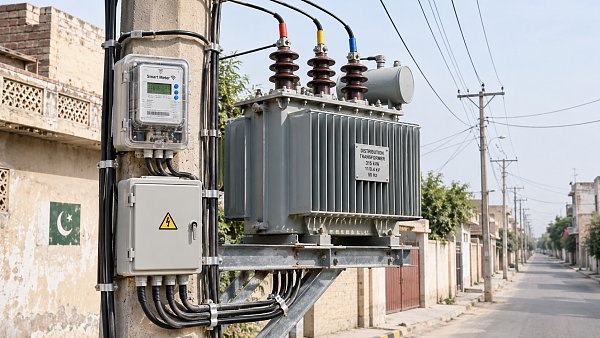
- Tamil Nadu Plans SIM-Based Upgrade for 17.7 Million Smart MetersTamil Nadu plans 17.7 million smart meters with proposed SIM-based upgrades. Explore potential supplier opportunities and the tender details still to come.
- Fiber Laser CE Marking: EU Safety Requirements and DocumentationFiber laser CE compliance goes beyond the mark. Explore EU safety requirements, essential documentation and practical checks before purchasing.
- US Grid Equipment Shortages Could Hinder $1 Trillion UpgradeUS grid equipment shortages could hinder a $1 trillion upgrade. Explore how transformer supply, data centers and rising power demand could affect grid projects.
Semiconductor Equipment Refurbishment Process: Cleaning to Qualification


A semiconductor tool is ready to return to production only when its restored condition is supported by measured evidence. The semiconductor equipment refurbishment process must connect contamination removal, component replacement, control-system verification, and process qualification to a defined operating envelope. A clean chamber and successful power-up establish very little about wafer contamination, process uniformity, or sustained operation.
Acceptance criteria therefore belong at the beginning of the work. They should identify the intended process, substrate format, material restrictions, facility interfaces, and required performance. Without that baseline, refurbishment can produce a functional machine whose suitability for the intended application remains unproven.
Establish the tool’s condition before disassembly
The incoming assessment should preserve evidence that cleaning and repairs would otherwise erase. Record the equipment identity, chamber configuration, installed options, software revisions, operating hours where available, alarm history, and maintenance records. Photographs should capture deposits, corrosion, damaged connectors, coolant staining, and modifications to gas or exhaust routing.
Previous process chemistry determines the decontamination strategy. Metal deposition, dielectric etching, ion implantation, and thermal processing leave different residues and create different material compatibility concerns. A chamber transferred between applications can introduce contamination even after its original deposits are no longer visible. Unknown service history creates an unresolved contamination question that must be addressed before selecting cleaning methods or assigning the tool to a sensitive process.
Before opening contaminated assemblies, residual hazards require assessment, isolation, and appropriate treatment. Gas lines, pumps, traps, and exhaust components can retain hazardous material after shutdown. An existing decontamination declaration provides useful history, but its scope must cover the assemblies actually being handled.
Where the incoming condition permits safe testing, baseline measurements help separate pre-existing faults from refurbishment-induced changes. Useful records include pump-down behavior, leak-test results, motion repeatability, temperature response, and sensor readings. Testing that requires energizing damaged or incompletely characterized systems should wait until those conditions have been resolved.
Cleaning must match the residue and the surface
Disassembly should follow a controlled component map. Parts require identification by chamber and position, especially where assemblies look interchangeable but have different wear histories or contamination exposure. Mixing hardware from incompatible process families can defeat otherwise effective cleaning.
Cleaning chemistry must remove the target residue while preserving the component’s working surface. Aluminum, stainless steel, quartz, ceramics, elastomers, and coated parts require different treatment. A method suitable for an uncoated metal shield could attack an anodized surface or alter a ceramic component. Aggressive treatment that changes roughness, dimensions, or coating integrity can increase particle generation after reassembly.
Ultrasonic cleaning also requires component-specific approval. Cavitation is useful for some robust parts, but fragile structures, bonded assemblies, and certain coatings require other methods. Sealed devices and precision assemblies should follow validated service procedures rather than being immersed as a default cleaning step.
Rinsing, drying, and handling are part of contamination control. Residual cleaning agents, trapped moisture, and contamination introduced by packaging can undermine an otherwise successful treatment. Blind holes and narrow passages deserve particular attention because retained liquid can later appear as slow vacuum recovery or unstable residual-gas readings.
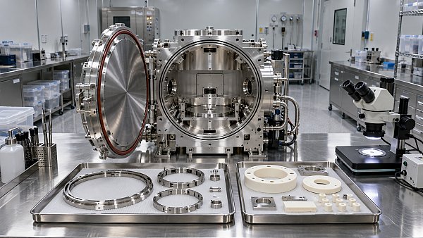
Cleaning verification must reflect the intended failure mechanism. Visual inspection detects gross residue, staining, and surface damage; it does not establish acceptable trace-metal levels or particle performance. Surface sampling, rinse analysis, residual-gas measurements, or witness-wafer testing should be selected according to the materials and process sensitivity. Each result needs an identified sampling location, method, and acceptance limit.
Some parts should be replaced rather than cleaned repeatedly. Cracked quartz, flaking coatings, damaged sealing surfaces, and eroded gas-distribution features can remain unsuitable after deposits have been removed. Recoated parts require evidence that the coating specification, dimensional condition, and preparation route remain appropriate for the application.
Restore subsystems against measurable requirements
Replacement decisions should distinguish consumable wear from loss of functional performance. A new component does not automatically reproduce the behavior of the original assembly. Differences in seal material, valve conductance, sensor range, or thermal contact can shift process behavior even when the replacement physically fits.
Vacuum diagnosis requires particular care because similar symptoms have different causes. A slow pump-down can result from a leak, moisture desorption, restricted conductance, or degraded pumping performance. Pressure-rise testing, leak detection, and residual-gas analysis provide different information; interpreting them together is more useful than assigning every pressure problem to the pump.
Gas-delivery verification must account for gas identity and calibration method. A controller calibrated with one gas cannot be treated as directly verified for another without a justified conversion or suitable calibration. Reactive and hazardous gas circuits also require compatible materials, verified isolation, and purge arrangements appropriate to the installed configuration.
For motion systems, repeatability must be evaluated across the actual transfer path. End-effector condition, robot teaching, lift-pin timing, and wafer-centering behavior interact. Repeated handling can reveal contact marks, edge damage, or particle generation that a single successful cycle misses.
Rebuild controls and safety functions as a complete configuration
Control-system work should preserve a traceable relationship between hardware, firmware, software, and recipes. Restoring an old backup without reconciling installed components can create incorrect scaling, missing interlocks, or incompatible communication settings. Before integration testing, record the approved configuration and verify the meaning of critical inputs and outputs.
Calibration should cover the installed measurement chain where its components affect the result. A calibrated sensor connected through an incorrectly scaled input still produces an incorrect displayed value. Records should identify the instrument, reference equipment, method, measurement range, results, and calibration status.
Safety verification must test the response to relevant faults, including loss of utilities and unsafe equipment states. Examples include cooling-flow loss, unavailable exhaust, pressure excursions, access-door opening, and emergency-stop activation. Acceptance depends on the resulting safe state and recovery behavior, including whether hazardous energy remains isolated until the required conditions are restored.
Applicable equipment safety requirements should be identified from the tool configuration, installation location, and refurbishment scope. Replacing a major controller or changing gas service can require a fresh assessment of affected functions. A generic statement that equipment is “standards compliant” is insufficient without identifying the requirements assessed, the configuration covered, and the supporting records.
Integration testing exposes faults that isolated tests miss
Subsystem tests establish local performance. Integration testing establishes whether the assembled tool behaves correctly through complete operating sequences. Load locks, transfer chambers, process chambers, utilities, and software must operate together without timing conflicts, communication faults, or unintended recovery actions.
Begin with controlled initialization and dry cycling, then introduce substrates and process conditions in stages. Exercise startup, normal operation, standby, shutdown, and recovery from representative interruptions. An intermittent vacuum fault or positioning error often appears only after thermal stabilization or repeated cycling.
The sequence of testing affects the diagnosis. Particle measurements taken immediately after chamber assembly can reflect loose assembly debris. Measurements taken after a defined conditioning sequence provide a different basis for acceptance. Both are useful when their purposes are clear, but results from different chamber states should not be compared as though the conditions were identical.
Integration records should capture trends as well as pass/fail outcomes. Increasing pump-down time, drifting matching positions, or growing temperature error can indicate developing instability even while individual cycles remain inside their limits. Investigating those patterns before process qualification reduces the chance that hardware behavior will be mistaken for a recipe problem.
Qualification must reproduce the intended process conditions
Final qualification needs a defined recipe, substrate, chamber condition, sampling plan, and measurement method. Equipment qualification and process qualification answer related but separate questions: the first establishes specified machine functions; the second establishes the required process result under stated conditions.
A deposition tool could meet requirements for thickness repeatability while failing contamination or within-wafer uniformity limits. An etch tool could achieve the target removal rate while producing unacceptable profile variation or substrate damage. Qualification metrics therefore need to reflect the intended application rather than whichever measurements are easiest to collect.
Particle testing requires controlled substrate handling and comparable pre-process and post-process measurements. Added-particle assessment depends on the measurement threshold, inspected area, wafer condition, and handling route. A particle count without those details cannot support a meaningful comparison between tools or refurbishment runs.
Repeatability should cover the operating variation relevant to production. Consecutive wafers address short-term behavior; runs separated by idle periods or chamber conditioning address other sources of variation. For multi-chamber equipment, each chamber needs an appropriate qualification basis, followed by matching evaluation where interchangeable processing is required.
Acceptance limits must be agreed before results are reviewed. Broadening a limit after a failed run obscures whether the equipment meets the intended requirement. Any deviation needs a documented technical disposition, corrective action where required, and retesting of the functions affected by the change. Replacing a seal after qualification, for example, can justify renewed vacuum and contamination verification.
Preserve the qualified state through shipment and installation
The release package should connect the incoming condition to the final configuration through cleaning records, component dispositions, replacement-part traceability, calibration results, safety tests, and qualification data. Raw measurements and test conditions make the results reviewable; a certificate stating only “tested and working” leaves the performance claim undefined.
Shipment and installation can change the qualified state. Transport restraints, protective packaging, storage conditions, and contamination barriers should suit the assemblies involved. At the destination, utility quality, exhaust behavior, grounding, vibration, and cooling conditions must be reconciled with the conditions used during testing.
Site acceptance should repeat the measurements most sensitive to transport and installation, followed by the agreed process confirmation. The final record should identify the configuration released for production, any unresolved restrictions, and the events that trigger requalification, such as major maintenance, software changes, or a change in process chemistry.
Recommended for You
 Smart MetersTamil Nadu Plans SIM-Based Upgrade for 17.7 Million Smart MetersTamil Nadu plans 17.7 million smart meters with proposed SIM-based upgrades. Explore potential supplier opportunities and the tender details still to come.By: Dr. Elena VoltNov 22, 2026
 Fiber LasersFiber Laser CE Marking: EU Safety Requirements and DocumentationFiber laser CE compliance goes beyond the mark. Explore EU safety requirements, essential documentation and practical checks before purchasing.By: Dr. Hideo TanakaNov 22, 2026
 Grid ResilienceUS Grid Equipment Shortages Could Hinder $1 Trillion UpgradeUS grid equipment shortages could hinder a $1 trillion upgrade. Explore how transformer supply, data centers and rising power demand could affect grid projects.By: Dr. Elena VoltNov 21, 2026
 Digital SeaChoosing Bluetooth Speakers: Sound Quality, Battery Life and PortabilityBluetooth speakers come in all shapes and sizes. Learn how to compare sound quality, battery life and portability to find the right fit for your listening needs.By: Captain Kenji SatoNov 21, 2026
 Subsea ROV/AUV2025 Ocean Equipment Report: China's Industry Moves Toward Scaled ApplicationChina's marine equipment industry is moving toward scaled application. Explore what the 2025 Ocean Equipment Report could mean for buyers, suppliers and offshore projects.By: Captain Kenji SatoNov 20, 2026
 Digital SeaChoosing a Thermoforming Vacuum Packaging Machine for Meat ProductsChoose a thermoforming vacuum packaging machine for meat with confidence. Compare sealing, film compatibility, hygiene and real-world production capacity.By: Captain Kenji SatoNov 20, 2026
 Digital SeaGreen Station Certification Cost: Fees and Budget ConsiderationsGreen station certification cost varies by scheme and site. Explore fees, hidden expenses, and budgeting tips to plan confidently and compare providers.By: Captain Kenji SatoNov 19, 2026
 UHV TransformersLIMiK Capital to Invest $328 Million in South Carolina Transformer PlantLIMiK Capital plans a $327.7 million transformer plant in South Carolina. Explore its potential impact on US grid supply and procurement.By: Dr. Elena VoltNov 18, 2026
 Digital SeaHow to Choose STEM Kits for Kids by Age, Interests, and Skill LevelChoose STEM kits that match your child's age, interests, and skills. Explore safety tips, project ideas, and practical checks to find an engaging fit.By: Captain Kenji SatoNov 18, 2026
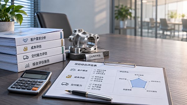
 Digital SeaManufacturing Supplier Requirements: What to Include in Technical SpecificationsDiscover how manufacturing technical specifications and supplier requirements improve quality, simplify comparisons, and prevent delays with measurable acceptance criteria.By: Captain Kenji SatoNov 17, 2026
 Digital SeaChina's Environment Ministry Opens ALC Submarine Cable Project to ReviewChina's Environment Ministry opens the ALC submarine cable project's environmental assessment to review. Explore the proposed marine protection measures and what comes next.By: Captain Kenji SatoNov 16, 2026
 Precision LensesOptical Lens Surface Roughness Testing: Methods and Ra InterpretationOptical lens surface roughness testing explained: compare measurement methods, interpret Ra values, and define reliable acceptance criteria.By: Dr. Hideo TanakaNov 16, 2026
 Digital SeaBusiness Growth Strategies: How to Choose the Right Path for Your CompanyExplore business growth strategies and learn how to compare market opportunities, costs, risks, and capabilities to choose the right path for your company.By: Captain Kenji SatoNov 15, 2026
 Smart MetersIndia’s Competition Commission Approves Adani Acquisition of IntelliSmartExplore the reported CCI approval of Adani’s IntelliSmart acquisition and what a larger Indian smart meter platform could mean for suppliers and investors.By: Dr. Elena VoltNov 14, 2026
 Digital SeaHow Does a Ballast Cleaner Screening System Separate Track Ballast?Discover how a ballast cleaner screening system separates reusable stone from fines, what affects performance, and how to assess the results.By: Captain Kenji SatoNov 14, 2026
 Smart MetersPakistan to Seek World Bank and ADB Funding for Smart MetersPakistan seeks World Bank and ADB funding for smart meters on distribution transformers. Explore the plan to tackle power theft and improve grid efficiency.By: Dr. Elena VoltNov 13, 2026
 Digital SeaWhat Is Precision Medicine and How Does It Guide Treatment?Discover how precision medicine uses biomarkers and genetic insights to guide treatment, where it can help, and what to ask before testing.By: Captain Kenji SatoNov 13, 2026
 Grid Resilience2026 CSEE Annual Meeting Opens with Focus on AI and Power SystemsThe 2026 CSEE Annual Meeting explores AI, low-carbon power systems and ultra-high-voltage transmission. Discover why these discussions matter.By: Dr. Elena VoltNov 12, 2026
 Digital SeaShip Radar Detection Range: How Far Can It See and What Limits It?Ship radar detection range depends on more than the display scale. Discover how antenna height, weather, target size, and settings affect what radar can see.By: Captain Kenji SatoNov 12, 2026
 UHV TransformersGE Vernova to Invest $34.5 Million in Louisiana Transformer Plant ExpansionGE Vernova plans a $34.5 million transformer plant expansion in Louisiana. Explore its potential impact on North American supply and procurement.By: Dr. Elena VoltNov 11, 2026
 Digital SeaMetro Station Noise Criteria: Limits and Measurement MethodsExplore metro station noise criteria, applicable limits and measurement methods. Learn how to select metrics and assess compliance with confidence.By: Captain Kenji SatoNov 11, 2026
 Digital SeaKongsberg Maritime Unveils Arctic Hunter Unmanned Surface VesselKongsberg Maritime's Arctic Hunter unmanned surface vessel is proposed for the Royal Navy's Type 92 programme. Explore its technology and procurement implications.By: Captain Kenji SatoNov 10, 2026
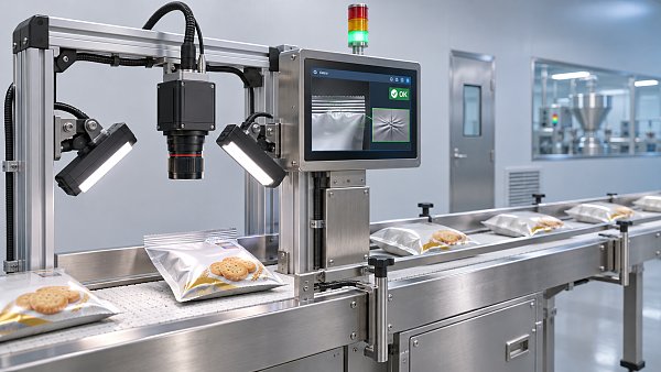
 Sorting RobotsHow Accurate Is AI in Food Quality Control? Metrics and Testing MethodsExplore AI in food quality control accuracy, from recall and false negatives to validation methods. Learn how to assess real-world inspection reliability.By: Marcus SterlingNov 10, 2026
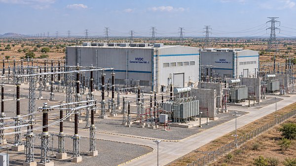
 UHV TransformersGE Vernova Selected for 6 GW HVDC Link in IndiaGE Vernova will design a 6 GW HVDC link for PGCIL, connecting Rajasthan and South Kalamb to support India's clean energy transition. Discover the project.By: Dr. Elena VoltNov 09, 2026
 Grid ResilienceEurope's Grid Compliance Standards in 2026: Generator Connection RequirementsExplore new grid compliance standards 2026 Europe projects must address, from generator connection rules to testing and documentation. Prepare for approval.By: Dr. Elena VoltNov 09, 2026
 Technical FabricsNonwoven Bonding Cost Data: Comparing Thermal and Chemical ProcessesExplore nonwoven bonding cost data to compare thermal and chemical processes, assess usable yield, and choose the best-value option for your application.By: Chloe DuboisNov 08, 2026
 Fiber LasersIndustrial Lasers to 2035: Automotive Lightweighting and Precision Welding Drive DemandExplore the industrial laser market outlook to 2035 and discover how automotive lightweighting and precision welding could shape demand and procurement.By: Dr. Hideo TanakaNov 07, 2026
 Technical FabricsChoosing Geotextile Under Railway Ballast: Key Performance RequirementsChoosing geotextile under railway ballast? Explore essential filtration, drainage, strength and durability criteria to make a confident, project-specific selection.By: Chloe DuboisNov 07, 2026
 Digital SeaChoosing Rail Welding Equipment for Maintenance: Field Conditions and Weld TypesChoose rail welding equipment for maintenance with confidence. Compare welding methods, field constraints, inspection needs, and lifecycle costs.By: Captain Kenji SatoNov 06, 2026
 Digital SeaIndia Broadband Forum Urges Stronger Submarine Cable ResilienceIndia’s submarine cable resilience is in focus as the Broadband India Forum urges faster repairs, more vessels and stronger landing infrastructure.By: Captain Kenji SatoNov 06, 2026
 Digital SeaChoosing a Railway Network Switch Supplier: Reliability and Support CriteriaChoosing a railway network switch supplier? Compare reliability, standards evidence, cybersecurity, and lifecycle support to reduce project risk.By: Captain Kenji SatoNov 05, 2026