BDI: 1,842 ▼ 1.2%
COTTON NO.2: 84.12 ▲ 0.4%
LME COPPER: 8,432.50 ▲ 2.1%
FOOD SAFETY INDEX: 94.2 ARCHIVE_SECURED
OPTICAL INDEX: 11,204.09 STABLE
BDI: 1,842 ▼ 1.2%

SECTOR INDEX
V.24.08 ARCHIVE
Hot Articles
- Tamil Nadu Plans SIM-Based Upgrade for 17.7 Million Smart MetersTamil Nadu plans 17.7 million smart meters with proposed SIM-based upgrades. Explore potential supplier opportunities and the tender details still to come.
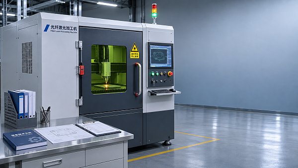
- Fiber Laser CE Marking: EU Safety Requirements and DocumentationFiber laser CE compliance goes beyond the mark. Explore EU safety requirements, essential documentation and practical checks before purchasing.
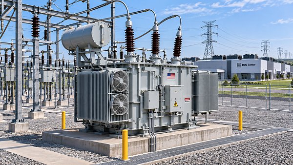
- US Grid Equipment Shortages Could Hinder $1 Trillion UpgradeUS grid equipment shortages could hinder a $1 trillion upgrade. Explore how transformer supply, data centers and rising power demand could affect grid projects.
Semiconductor Equipment Overhaul: Diagnosing Persistent Process Drift


Semiconductor Equipment Overhaul: Diagnosing Persistent Process Drift
Persistent process drift after a semiconductor equipment overhaul can leave maintenance teams chasing unstable readings, repeat service calls, and unresolved yield losses. When routine calibration fails to restore consistency, the cause may lie in chamber conditioning, sensor bias, vacuum integrity, or thermal control—not simply a worn component.
The difficult cases are often machines that pass static checks but change behavior during production. Base pressure looks acceptable, temperature reaches setpoint, and no interlock trips. Yet film thickness, etch rate, uniformity, or endpoint timing moves across successive wafers. Resolving this requires connecting the service history to process trends, then testing specific explanations without changing several variables at once.
Establish whether the process moved—or the measurement did
Before reopening the tool, verify the evidence. A shift in film thickness can originate in the process chamber, but it can also reflect a changed metrology recipe, optical model, sampling location, or reference condition. Compare results using the same measurement method and check the metrology tool against its approved reference procedure. Independent measurement, where available and suitable, helps separate a process change from a reporting problem.
Describe the deviation precisely. A stable offset after maintenance is different from a gradual wafer-to-wafer trend. A repeating spatial pattern points toward different mechanisms than random excursions. Record whether the effect follows elapsed time, processed wafer count, cumulative plasma exposure, idle duration, or a particular recipe transition.
Use a valid pre-overhaul baseline: the same qualified recipe, comparable incoming material, consistent sampling, and known chamber condition. A sister chamber can provide context, but it is not automatically an interchangeable reference. Hardware configuration, consumable age, and accumulated coating history may differ.
Reconstruct what changed during the overhaul
“Chamber serviced” is not enough detail for root-cause analysis. Build a change record that includes replaced parts, cleaned surfaces, seal materials, sensor work, controller settings, firmware, and utility connections. Check actual installed part numbers and revisions against the approved configuration rather than relying only on the purchase description.
Pay particular attention to components that change geometry or surface behavior: liners, showerheads, focus rings, electrodes, shields, and wafer supports. Depending on the process, a replacement can alter gas distribution, plasma coupling, thermal contact, or surface reactions even when it fits correctly. Cleaning residues and handling contamination also deserve consideration.
Recover controller backups and calibration records where available. A sensor replacement accompanied by a changed scaling factor can create an apparent process shift. A reset throttle controller may hold average pressure while producing different transient behavior. These changes are easily missed when the service report records only mechanical work.
Let the drift pattern determine the next test
Trend the process result alongside time-aligned equipment data. Useful channels may include chamber pressure, throttle position, gas-flow readback, heater output, coolant conditions, RF forward and reflected power, and endpoint signals. Capture recipe transitions as well as steady-state values; averages can hide delayed settling or oscillation.
- Improvement across successive conditioning wafers: investigate chamber surface stabilization and thermal equilibration before assuming another component has failed.
- Deterioration after idle periods: examine moisture exposure, temperature recovery, gas-line stabilization, and the approved restart sequence.
- Stable pressure with changing throttle position: investigate changes in gas load, pumping conductance, or gauge behavior. Position alone does not identify the cause.
- Recurring radial or edge-related variation: check wafer seating, thermal contact, edge hardware, and gas-distribution geometry.
- Similar shifts across several tools: check shared utilities, incoming material, and metrology before repeating chamber-level repairs.
These are diagnostic leads, not verdicts. The useful question is: what controlled observation would distinguish one explanation from another? Define that observation before starting the test.
Check vacuum and gas delivery under process-relevant conditions
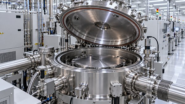
Passing a base-pressure check does not prove that the vacuum system behaves correctly under gas flow, elevated temperature, or wafer transfer. Compare pumpdown curves with an appropriate historical reference. Where permitted by the equipment procedure, rate-of-rise testing can help characterize gas loading, although it does not by itself distinguish external leakage from outgassing.
If leakage is suspected, use the approved leak-detection procedure with attention to recently disturbed seals, feedthroughs, and connections. Confirm instrument readiness and test conditions. Residual gas analysis, where available, can provide supporting evidence about water or contamination, but interpretation depends on operating conditions and instrument limitations.
For gas delivery, distinguish a controller’s displayed flow from independently verified delivery. Check gas configuration, inlet-pressure requirements, zeroing conditions, and valve response against manufacturer instructions. Inspect disturbed lines and connections, and verify purge completion before qualified testing.
Do not apply improvised leak tests or substitute gases without an approved method. Hazardous process gases, stored energy, RF systems, and vacuum hardware require trained personnel, appropriate isolation, and site safety controls. Diagnostic urgency does not justify bypassing interlocks.
Separate sensor accuracy from actual process conditions
A calibrated sensor can still provide an unrepresentative measurement. Installation position, thermal exposure, contamination, signal conditioning, and grounding can all matter. For pressure measurement, confirm gauge type, usable range, zeroing procedure, and any applicable gas dependence. Agreement at one test point does not establish accuracy throughout the recipe.
Temperature deserves particular scrutiny because heater setpoint is not wafer temperature. After overhaul, changed contact surfaces, sensor placement, backside-gas behavior, or cooling conditions may alter heat transfer while the displayed temperature remains stable. Review heater output and settling behavior alongside temperature feedback. An unusual increase in control effort can reveal a disturbance that the loop is compensating for.
Where the tool supports it, use approved wafer-temperature characterization or an appropriate reference method. Also check coolant supply temperature, flow, and return behavior under load. An idle utility reading may miss a restriction or load-dependent fluctuation.
On plasma tools, examine RF delivery as a system. Cable reconnection, grounding, matching-network behavior, electrode condition, and chamber geometry can affect coupling. Generator power readback alone does not establish identical plasma conditions. Interpret electrical trends together with process measurements and approved diagnostic signals.
Why repeated calibration can make diagnosis harder
Adjusting offsets until monitor wafers pass can conceal the original fault. A pressure correction might compensate for gauge bias while leaving a conductance problem unresolved. A recipe adjustment may temporarily recover thickness while masking unstable chamber conditioning. Preserve the original settings, document every authorized change, and avoid using recipe compensation as proof that hardware has recovered.
Treat chamber conditioning as a controlled recovery step
Cleaning and replacing chamber components changes the surfaces exposed to the process. In deposition and etch systems, those surfaces can influence adsorption, desorption, and reactive-species balance. This is why mechanically correct reassembly does not necessarily produce immediate process equivalence.
Follow the equipment- and process-specific conditioning sequence. Record the recipe, wafer or substrate type, exposure history, idle intervals, and monitor results. Do not assume that a fixed number of seasoning cycles proves recovery. The evidence should show convergence toward the qualified process window and repeatability under defined operating conditions.
Set an approved review point rather than conditioning indefinitely. If the trend fails to converge, returns after a short idle, or requires repeated compensation, revisit contamination, component compatibility, temperature control, and vacuum integrity. More seasoning is not a substitute for investigating a persistent fault.
Close the investigation with evidence, not a single passing wafer
Before each corrective action, state the suspected mechanism and predicted result. If a cooling restriction is responsible, correcting it should change thermal recovery behavior as well as the associated process trend. If only the final wafer result improves, the explanation may remain incomplete. Keep other variables fixed where practical; use a controlled experimental plan when interactions cannot be separated.
Return-to-production criteria should be agreed with process engineering and quality personnel before qualification begins. They should address:
- Process results within approved limits, including relevant uniformity, particle, and repeatability requirements.
- Stable behavior across the production sequence being qualified, including restart or recipe transitions where applicable.
- Equipment traces consistent with the accepted operating envelope, without unexplained compensation or alarms.
- Complete configuration, calibration, service, and corrective-action records, with defined post-release monitoring and escalation triggers.
There is no universal wafer count or tolerance for closing a semiconductor equipment overhaul. The appropriate evidence depends on the process, equipment design, product risk, and site qualification requirements.
G-MCE’s cross-disciplinary technical benchmarking perspective is relevant here: replacement hardware should be assessed through traceable specifications, material compatibility, calibration evidence, and configuration control—not nominal equivalence alone. Its broader industrial intelligence role complements that comparison; it does not replace semiconductor OEM procedures or process qualification.
For the next service review, bring synchronized trend files, the detailed overhaul change list, metrology checks, and the results of controlled tests. That evidence gives maintenance, process engineering, and the equipment supplier a practical basis for deciding whether to reopen the chamber, correct a utility problem, revise conditioning, or authorize a monitored production release.
Recommended for You
 Smart MetersTamil Nadu Plans SIM-Based Upgrade for 17.7 Million Smart MetersTamil Nadu plans 17.7 million smart meters with proposed SIM-based upgrades. Explore potential supplier opportunities and the tender details still to come.By: Dr. Elena VoltNov 22, 2026
 Fiber LasersFiber Laser CE Marking: EU Safety Requirements and DocumentationFiber laser CE compliance goes beyond the mark. Explore EU safety requirements, essential documentation and practical checks before purchasing.By: Dr. Hideo TanakaNov 22, 2026
 Grid ResilienceUS Grid Equipment Shortages Could Hinder $1 Trillion UpgradeUS grid equipment shortages could hinder a $1 trillion upgrade. Explore how transformer supply, data centers and rising power demand could affect grid projects.By: Dr. Elena VoltNov 21, 2026
 Digital SeaChoosing Bluetooth Speakers: Sound Quality, Battery Life and PortabilityBluetooth speakers come in all shapes and sizes. Learn how to compare sound quality, battery life and portability to find the right fit for your listening needs.By: Captain Kenji SatoNov 21, 2026
 Subsea ROV/AUV2025 Ocean Equipment Report: China's Industry Moves Toward Scaled ApplicationChina's marine equipment industry is moving toward scaled application. Explore what the 2025 Ocean Equipment Report could mean for buyers, suppliers and offshore projects.By: Captain Kenji SatoNov 20, 2026
 Digital SeaChoosing a Thermoforming Vacuum Packaging Machine for Meat ProductsChoose a thermoforming vacuum packaging machine for meat with confidence. Compare sealing, film compatibility, hygiene and real-world production capacity.By: Captain Kenji SatoNov 20, 2026
 Digital SeaGreen Station Certification Cost: Fees and Budget ConsiderationsGreen station certification cost varies by scheme and site. Explore fees, hidden expenses, and budgeting tips to plan confidently and compare providers.By: Captain Kenji SatoNov 19, 2026
 UHV TransformersLIMiK Capital to Invest $328 Million in South Carolina Transformer PlantLIMiK Capital plans a $327.7 million transformer plant in South Carolina. Explore its potential impact on US grid supply and procurement.By: Dr. Elena VoltNov 18, 2026
 Digital SeaHow to Choose STEM Kits for Kids by Age, Interests, and Skill LevelChoose STEM kits that match your child's age, interests, and skills. Explore safety tips, project ideas, and practical checks to find an engaging fit.By: Captain Kenji SatoNov 18, 2026
 Digital SeaManufacturing Supplier Requirements: What to Include in Technical SpecificationsDiscover how manufacturing technical specifications and supplier requirements improve quality, simplify comparisons, and prevent delays with measurable acceptance criteria.By: Captain Kenji SatoNov 17, 2026
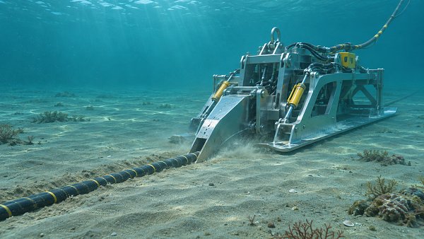
 Digital SeaChina's Environment Ministry Opens ALC Submarine Cable Project to ReviewChina's Environment Ministry opens the ALC submarine cable project's environmental assessment to review. Explore the proposed marine protection measures and what comes next.By: Captain Kenji SatoNov 16, 2026
 Precision LensesOptical Lens Surface Roughness Testing: Methods and Ra InterpretationOptical lens surface roughness testing explained: compare measurement methods, interpret Ra values, and define reliable acceptance criteria.By: Dr. Hideo TanakaNov 16, 2026
 Digital SeaBusiness Growth Strategies: How to Choose the Right Path for Your CompanyExplore business growth strategies and learn how to compare market opportunities, costs, risks, and capabilities to choose the right path for your company.By: Captain Kenji SatoNov 15, 2026
 Smart MetersIndia’s Competition Commission Approves Adani Acquisition of IntelliSmartExplore the reported CCI approval of Adani’s IntelliSmart acquisition and what a larger Indian smart meter platform could mean for suppliers and investors.By: Dr. Elena VoltNov 14, 2026
 Digital SeaHow Does a Ballast Cleaner Screening System Separate Track Ballast?Discover how a ballast cleaner screening system separates reusable stone from fines, what affects performance, and how to assess the results.By: Captain Kenji SatoNov 14, 2026
 Smart MetersPakistan to Seek World Bank and ADB Funding for Smart MetersPakistan seeks World Bank and ADB funding for smart meters on distribution transformers. Explore the plan to tackle power theft and improve grid efficiency.By: Dr. Elena VoltNov 13, 2026
 Digital SeaWhat Is Precision Medicine and How Does It Guide Treatment?Discover how precision medicine uses biomarkers and genetic insights to guide treatment, where it can help, and what to ask before testing.By: Captain Kenji SatoNov 13, 2026
 Grid Resilience2026 CSEE Annual Meeting Opens with Focus on AI and Power SystemsThe 2026 CSEE Annual Meeting explores AI, low-carbon power systems and ultra-high-voltage transmission. Discover why these discussions matter.By: Dr. Elena VoltNov 12, 2026
 Digital SeaShip Radar Detection Range: How Far Can It See and What Limits It?Ship radar detection range depends on more than the display scale. Discover how antenna height, weather, target size, and settings affect what radar can see.By: Captain Kenji SatoNov 12, 2026
 UHV TransformersGE Vernova to Invest $34.5 Million in Louisiana Transformer Plant ExpansionGE Vernova plans a $34.5 million transformer plant expansion in Louisiana. Explore its potential impact on North American supply and procurement.By: Dr. Elena VoltNov 11, 2026
 Digital SeaMetro Station Noise Criteria: Limits and Measurement MethodsExplore metro station noise criteria, applicable limits and measurement methods. Learn how to select metrics and assess compliance with confidence.By: Captain Kenji SatoNov 11, 2026
 Digital SeaKongsberg Maritime Unveils Arctic Hunter Unmanned Surface VesselKongsberg Maritime's Arctic Hunter unmanned surface vessel is proposed for the Royal Navy's Type 92 programme. Explore its technology and procurement implications.By: Captain Kenji SatoNov 10, 2026
 Sorting RobotsHow Accurate Is AI in Food Quality Control? Metrics and Testing MethodsExplore AI in food quality control accuracy, from recall and false negatives to validation methods. Learn how to assess real-world inspection reliability.By: Marcus SterlingNov 10, 2026
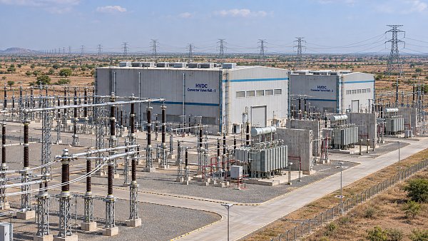
 UHV TransformersGE Vernova Selected for 6 GW HVDC Link in IndiaGE Vernova will design a 6 GW HVDC link for PGCIL, connecting Rajasthan and South Kalamb to support India's clean energy transition. Discover the project.By: Dr. Elena VoltNov 09, 2026
 Grid ResilienceEurope's Grid Compliance Standards in 2026: Generator Connection RequirementsExplore new grid compliance standards 2026 Europe projects must address, from generator connection rules to testing and documentation. Prepare for approval.By: Dr. Elena VoltNov 09, 2026
 Technical FabricsNonwoven Bonding Cost Data: Comparing Thermal and Chemical ProcessesExplore nonwoven bonding cost data to compare thermal and chemical processes, assess usable yield, and choose the best-value option for your application.By: Chloe DuboisNov 08, 2026
 Fiber LasersIndustrial Lasers to 2035: Automotive Lightweighting and Precision Welding Drive DemandExplore the industrial laser market outlook to 2035 and discover how automotive lightweighting and precision welding could shape demand and procurement.By: Dr. Hideo TanakaNov 07, 2026
 Technical FabricsChoosing Geotextile Under Railway Ballast: Key Performance RequirementsChoosing geotextile under railway ballast? Explore essential filtration, drainage, strength and durability criteria to make a confident, project-specific selection.By: Chloe DuboisNov 07, 2026
 Digital SeaChoosing Rail Welding Equipment for Maintenance: Field Conditions and Weld TypesChoose rail welding equipment for maintenance with confidence. Compare welding methods, field constraints, inspection needs, and lifecycle costs.By: Captain Kenji SatoNov 06, 2026
 Digital SeaIndia Broadband Forum Urges Stronger Submarine Cable ResilienceIndia’s submarine cable resilience is in focus as the Broadband India Forum urges faster repairs, more vessels and stronger landing infrastructure.By: Captain Kenji SatoNov 06, 2026
 Digital SeaChoosing a Railway Network Switch Supplier: Reliability and Support CriteriaChoosing a railway network switch supplier? Compare reliability, standards evidence, cybersecurity, and lifecycle support to reduce project risk.By: Captain Kenji SatoNov 05, 2026