BDI: 1,842 ▼ 1.2%
COTTON NO.2: 84.12 ▲ 0.4%
LME COPPER: 8,432.50 ▲ 2.1%
FOOD SAFETY INDEX: 94.2 ARCHIVE_SECURED
OPTICAL INDEX: 11,204.09 STABLE
BDI: 1,842 ▼ 1.2%

SECTOR INDEX
V.24.08 ARCHIVE
Hot Articles
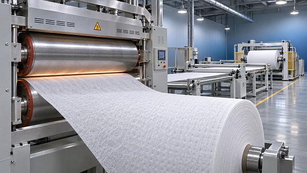
- Nonwoven Bonding Cost Data: Comparing Thermal and Chemical ProcessesExplore nonwoven bonding cost data to compare thermal and chemical processes, assess usable yield, and choose the best-value option for your application.
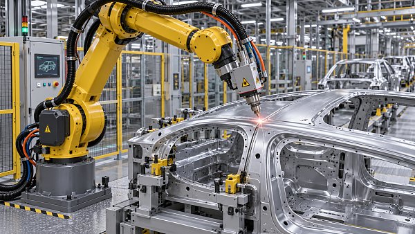
- Industrial Lasers to 2035: Automotive Lightweighting and Precision Welding Drive DemandExplore the industrial laser market outlook to 2035 and discover how automotive lightweighting and precision welding could shape demand and procurement.
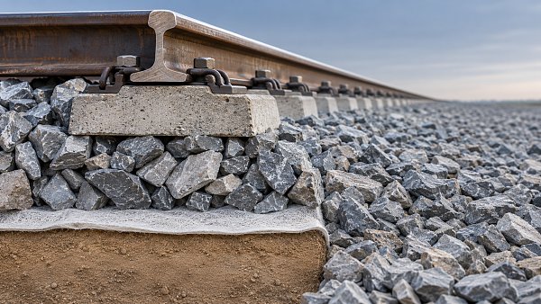
- Choosing Geotextile Under Railway Ballast: Key Performance RequirementsChoosing geotextile under railway ballast? Explore essential filtration, drainage, strength and durability criteria to make a confident, project-specific selection.
How to reduce thermal drift in precision lens positioning systems


The most effective way to reduce thermal drift in precision lens positioning is to stabilize the entire path between the lens and its optical reference—not just the moving stage. A high-resolution encoder can report a stationary carriage while the lens mount, support frame, or image plane moves with temperature. Closed-loop positioning only corrects motion that its feedback system can actually observe.
A robust solution combines reduced heat generation, predictable mechanical expansion, controlled temperature gradients, and feedback referenced to the right location. Temperature-based compensation becomes useful after these measures make the remaining drift repeatable. If thermal behavior depends strongly on motion history, airflow, or mounting stress, a simple correction coefficient will not reliably restore alignment.
Define the error at the optical interface
Thermal drift should be specified as a change in useful optical performance over a defined operating condition. Depending on the application, that could mean lens-to-sensor spacing, lateral decenter, angular alignment, focal-plane position, or coupling efficiency. These quantities are related, but they are not interchangeable.
For example, maintaining the mechanical position of a focusing lens does not necessarily maintain focus. Temperature changes can alter lens curvature, thickness, and refractive index, shifting the focal plane even when the mount remains stationary. Conversely, a thermally expanding support may move the lens in a direction that partially offsets its optical focus shift. Such cancellation must be modeled and verified rather than assumed.
Before changing hardware, establish:
- The optical reference: detector plane, another lens group, a workpiece, or a fiber interface.
- The allowable axial, lateral, and angular errors, including any temperature-driven optical changes.
- The relevant thermal conditions: ambient variation, internal self-heating, startup, and changes in operating duty cycle.
- The time interval over which stability matters, such as one exposure, a scan, or continuous operation.
A system that is stable after thermal equilibrium may still be unsuitable for measurements taken immediately after power-up. Likewise, slow drift across a shift and rapid drift during a scan require different mitigation.
Trace the expansion path before choosing materials
A useful first estimate for an unconstrained component is ΔL = αLΔT, where α is the coefficient of thermal expansion, L is its effective length, and ΔT is its temperature change. Using an approximate aluminum coefficient of 23 × 10−6/K, a 50 mm member undergoing a uniform 2 K increase expands by about 2.3 µm. This is an illustrative calculation, not a prediction of assembled-system drift.
The actual displacement depends on which members expand, their directions, their constraints, and where the reference is located. Expansion in two supports can cancel relative motion, add to it, or produce tilt. A short mount close to a heat source can matter more than a long base that remains thermally stable.
Trace two paths from a common structural reference: one to the lens’s mechanically defined datum and one to the optical target or detector. Include the carriage, bearings or flexures, mounting brackets, fasteners, adhesives, and detector support. Then examine the feedback path separately. Any segment outside that measurement loop can drift without being corrected.

Uniform temperature change is only part of the problem. Unequal heating across a bracket can bend it; different temperatures at two supports can tilt the lens. Angular motion also creates position error when the measurement axis is offset from the optical axis. For small angles, this Abbe error is approximately the offset distance multiplied by the angular change. Reducing that offset can therefore improve thermal performance without changing the encoder resolution.
Temperature measurements should follow this structural map. Sensors near the actuator, lens mount, base, and optical reference are more informative than a single enclosure-air reading. Contact quality and sensor response time matter: the measured temperature must represent the component responsible for displacement, not merely the surrounding air.
Reduce heat generation and make heat flow predictable
Internal heating can dominate even in a temperature-controlled room. Motors, piezoelectric drivers, control electronics, illumination sources, and nearby cameras can create local gradients. Their thermal effects depend on operating mode, so a stationary qualification test may miss drift generated by repeated moves or sustained holding current.
Motor heating can be reduced by lowering holding current where load stability permits, avoiding unnecessary servo activity, and selecting an actuator suited to the required force and duty cycle. Any reduction must be checked against holding stiffness, settling behavior, and disturbance rejection. Lower heat is not an improvement if the lens becomes mechanically unstable.
Piezoelectric actuation is not automatically heat-free. Dissipation depends on drive frequency, voltage, capacitance, and dielectric losses. A piezo stage that performs well during occasional adjustments may behave differently under continuous modulation. Similarly, motorized screws and bearings can introduce frictional heating during repetitive travel.
Place heat-producing electronics away from the lens-support structure where practical, and provide a deliberate conductive path to a stable heat sink. Thermal isolation helps when it blocks an external heat source, but it can worsen drift if it traps actuator heat. Flexible heat straps also need evaluation for parasitic force and stiffness throughout travel.
Airflow introduces another trade-off. Fans can remove heat while creating vibration and uneven cooling. An enclosure may reduce drafts but retain internal heat. The relevant question is whether the arrangement lowers temperature variation and gradients at the critical mechanical paths—not whether it simply lowers the enclosure’s average temperature.
Use material selection together with geometry and mounting design
Low-expansion materials are valuable when structural expansion dominates the error budget, but replacing an aluminum bracket with a low-expansion alloy is not a complete thermal design. Thermal conductivity, stiffness, mass, joining methods, and heat distribution also affect performance. A low-expansion structure can still deform under gradients or transmit stress into the optic.
A compact, symmetric arrangement often offers a more direct improvement. Shortening the distance between the lens and its reference reduces expansion sensitivity. Symmetric support paths can make expansion more nearly common-mode, reducing relative motion. These benefits disappear if the nominally symmetric sides experience different heat loads or mounting constraints.
Lens retention deserves particular attention. Differential expansion between the glass and barrel can change clamping force, decenter the optic, or distort its surface. Tight radial capture may preserve room-temperature alignment while introducing thermal stress. Compliant retention, controlled preload, or suitable flexure arrangements can accommodate expansion, provided they retain adequate shock resistance and alignment stiffness.
Flexures avoid sliding friction and backlash, but remain sensitive to material expansion and asymmetric heating. Adhesive joints likewise require scrutiny: bond thickness, expansion mismatch, creep, and cure-induced stress can affect alignment. If alignment does not return after a heating-and-cooling cycle, the mechanism may involve stress relaxation or slip rather than reversible expansion. Temperature compensation alone will not resolve that behavior.
Close the loop around the quantity that must remain stable
Encoder resolution is not equivalent to thermal positioning accuracy. An encoder mounted between a carriage and its base measures that local relationship. It does not necessarily detect movement of the lens within its holder, movement of the detector, or changes in optical focus.
Direct displacement sensing is useful when mechanical spacing is the controlled quantity. Capacitive sensors and interferometric systems can provide sensitive measurements, but their own thermal and environmental effects must be included. Air-path interferometry, for example, requires attention to refractive-index changes if the required uncertainty makes them significant.
Optical feedback can capture both mechanical and thermo-optic effects. An autofocus metric may restore image focus, but a single axial correction cannot necessarily repair decenter, tilt, or thermally induced aberration. It can also confuse scene changes with focus changes unless the measurement method separates them.
Keep the metrology axis close to the optical axis and anchor the sensor reference to the structure that defines useful alignment. A fast inner positioning loop can be combined with a slower thermal or optical correction loop. Their bandwidths and command limits should prevent interaction, hunting, and excessive response to measurement noise.
Add compensation only after drift becomes repeatable
A correction such as Δx = k(T − Tref) is useful when position changes reproducibly with the measured temperature over the calibrated range. It is less reliable during warm-up, when different components heat at different rates. The same sensor reading can correspond to different lens positions during heating and cooling.
If thermal lag is significant, compensation may need several temperature inputs and a dynamic model. Actuator duty cycle or electrical power can provide additional information about changing heat loads. Model complexity should be justified by measurements: adding variables does not guarantee better prediction outside the calibration conditions.
Calibrate across representative operating modes, including idle periods, repeated motion, and relevant illumination states. Validate the model using separate runs rather than only the data used to fit it. Check residual error, heating-versus-cooling behavior, and sensitivity to initial temperature.
Preserve sufficient actuator travel for correction, and define behavior when sensors fail or temperatures leave the validated range. Unrestricted extrapolation can drive the lens away from the useful operating point.
Validate stability under the conditions that generate drift
A credible thermal test must distinguish device behavior from measurement-fixture drift. The external reference, fixtures, and measurement uncertainty should be stable enough to resolve the required error. Otherwise, an apparent lens displacement may originate in the test setup.
Test ambient changes separately from internal heat-load changes before combining them. Record position or optical performance alongside temperatures at the relevant structural locations, actuator activity, and operating state. Include startup from a defined initial condition, representative motion sequences, temperature ramps where applicable, and heating-and-cooling cycles.
Assess transient peak error, drift rate, steady-state offset, return-to-baseline error, and cycle-to-cycle repeatability. A steady-state average can conceal a short excursion that invalidates an exposure. Residual error after cooling can reveal mounting changes that a linear expansion model misses.
Testing should also retain the intended orientation, cable routing, payload, enclosure, and controller settings. Cable forces can change as temperature and carriage position change; mounting preload and gravity can alter how expansion appears at the lens. Acceptance limits should therefore specify both thermal conditions and operating conditions, rather than relying on an unexplained “thermal stability” value.
When the measured error is dominated by support expansion, shorten or stabilize the structural path. When gradients produce tilt, address heat flow and symmetry. When drift occurs outside the encoder loop, move the measurement reference closer to the optical interface. When the mechanics remain stable but focus shifts, evaluate thermo-optic behavior and optical correction. This diagnosis-led approach reduces drift at its source instead of asking compensation to conceal an unstable design.
Recommended for You
 Technical FabricsNonwoven Bonding Cost Data: Comparing Thermal and Chemical ProcessesExplore nonwoven bonding cost data to compare thermal and chemical processes, assess usable yield, and choose the best-value option for your application.By: Chloe DuboisNov 08, 2026
 Fiber LasersIndustrial Lasers to 2035: Automotive Lightweighting and Precision Welding Drive DemandExplore the industrial laser market outlook to 2035 and discover how automotive lightweighting and precision welding could shape demand and procurement.By: Dr. Hideo TanakaNov 07, 2026
 Technical FabricsChoosing Geotextile Under Railway Ballast: Key Performance RequirementsChoosing geotextile under railway ballast? Explore essential filtration, drainage, strength and durability criteria to make a confident, project-specific selection.By: Chloe DuboisNov 07, 2026
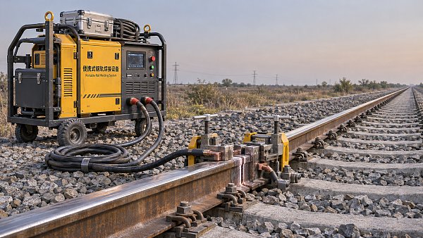
 Digital SeaChoosing Rail Welding Equipment for Maintenance: Field Conditions and Weld TypesChoose rail welding equipment for maintenance with confidence. Compare welding methods, field constraints, inspection needs, and lifecycle costs.By: Captain Kenji SatoNov 06, 2026
 Digital SeaIndia Broadband Forum Urges Stronger Submarine Cable ResilienceIndia’s submarine cable resilience is in focus as the Broadband India Forum urges faster repairs, more vessels and stronger landing infrastructure.By: Captain Kenji SatoNov 06, 2026
 Digital SeaChoosing a Railway Network Switch Supplier: Reliability and Support CriteriaChoosing a railway network switch supplier? Compare reliability, standards evidence, cybersecurity, and lifecycle support to reduce project risk.By: Captain Kenji SatoNov 05, 2026
 Grid ResilienceUS Grid Equipment Import Ban Raises Cost and Implementation ConcernsThe US grid equipment import ban raises concerns over costs and delivery delays. Explore how unclear criteria could affect procurement and supply chains.By: Dr. Elena VoltNov 05, 2026
 Digital SeaRailway Coupler Price: How Type and Specifications Affect QuotesRailway coupler price depends on type, specifications, and order scope. Learn how to compare quotes, avoid hidden costs, and make a confident buying decision.By: Captain Kenji SatoNov 04, 2026
 Grid ResilienceGlobal Smart Grid Companies Raise $3 Billion in First Nine Months of 2026Global smart grid companies raised $3 billion in the first nine months of 2026. Explore the funding breakdown and potential implications for buyers and suppliers.By: Dr. Elena VoltNov 04, 2026
 Digital SeaChoosing Wholesale Pet Toys: How to Evaluate Suppliers and Minimum OrdersWholesale pet toys: learn how to assess suppliers, compare minimum orders and landed costs, and reduce inventory risk before you buy.By: Captain Kenji SatoNov 03, 2026
 Digital SeaSustainable Packaging Design: How to Choose Materials and Reduce WasteDiscover how sustainable packaging design helps reduce waste, protect products, and control costs with practical material choices and proven testing strategies.By: Captain Kenji SatoNov 02, 2026
 Technical FabricsUSMCA's First Joint Review Puts Textile Supply Chain Rules in FocusUSMCA's first joint review puts textile supply chain rules in focus. Explore potential impacts on origin compliance, sourcing and tariff treatment.By: Chloe DuboisNov 02, 2026
 Digital SeaManufacturing KPI Benchmarking: How to Compare Production PerformanceBenchmarking KPI manufacturing performance? Learn how to compare OEE, quality and downtime, identify meaningful gaps, and turn insights into practical improvements.By: Captain Kenji SatoNov 01, 2026
 Smart MetersCCI Approves Adani Energy Solutions' ₹305 Billion Acquisition of IntelliSmartCCI approves Adani Energy Solutions' ₹305 billion acquisition of IntelliSmart. Discover what the deal could mean for India's smart meter market.By: Dr. Elena VoltNov 01, 2026
 Digital SeaChoosing a Coin Laundry Machinery OEM: What Buyers Should EvaluateChoosing a coin laundry machinery OEM? Compare machine specifications, payment integration, lifecycle costs, and support to make a confident buying decision.By: Captain Kenji SatoOct 31, 2026
 Grid ResilienceUS Energy Department Announces $237 Million Grid SCALED Funding ProgramExplore the DOE's $237 million Grid SCALED funding program and its goals to strengthen grid equipment supply chains, lower electricity costs, and improve resilience.By: Dr. Elena VoltOct 31, 2026
 UHV TransformersA Decade of UHV Power in Shandong: Province Leads in Station NumbersShandong UHV power leads China in station numbers. Explore a decade of grid development and its implications for electricity supply and business planning.By: Dr. Elena VoltOct 30, 2026
 Digital SeaChoosing a Composite Train Body Panel Manufacturer: Fire Safety and Quality ChecksChoosing a composite train body panels manufacturer? Learn how to verify fire test evidence, audit production quality, and avoid costly approval gaps before you buy.By: Captain Kenji SatoOct 29, 2026
 Subsea ROV/AUVOcean Infinity Deploys Six AUVs Together Beyond 5,000 MetresOcean Infinity reportedly deployed six HUGIN AUVs beyond 5,200 metres. Explore what concurrent deepwater missions could mean for seabed surveys and procurement.By: Captain Kenji SatoOct 29, 2026
 Grid ResilienceRenewable Energy Grid Balancing: How Storage and Demand Response Work TogetherExplore renewable energy grid balancing with storage and demand response. Learn how coordinated controls manage shortfalls, absorb surplus power, and improve grid reliability.By: Dr. Elena VoltOct 28, 2026
 Subsea ROV/AUVSeaber Introduces 13 kg RAVEN AUV to Target Mine Countermeasure CostsSeaber’s 13 kg RAVEN AUV targets lower mine countermeasure costs with two mission configurations. Explore its potential value for naval operations and procurement.By: Captain Kenji SatoOct 28, 2026
 Digital SeaBallast Water Management Rules: IMO vs. USCG Compliance RequirementsBallast water management rules explained: compare IMO and USCG approvals, operating limits, and records. Get practical checks to reduce compliance risks and costly port delays.By: Captain Kenji SatoOct 27, 2026
 Subsea ROV/AUVEni Signs Main Cronos Contracts, Moving Gas Project into ExecutionEni’s Cronos gas project enters execution as major contracts are signed. Explore the Cyprus development, Egypt processing plans and key milestones toward first gas in 2028.By: Captain Kenji SatoOct 27, 2026
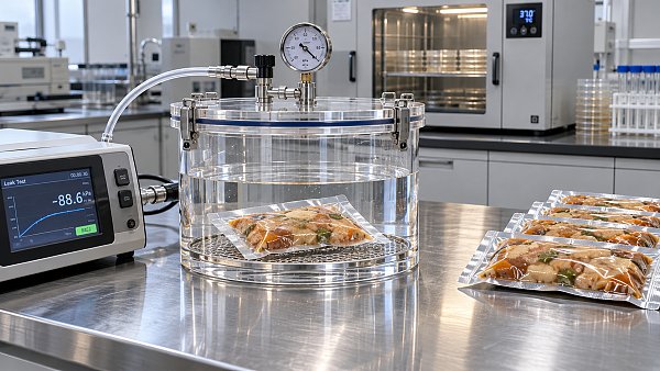
 Aseptic FillingWhich Tests Verify Commercial Sterility in Aseptically Filled Foods?Explore aseptic filled food tests, from incubation and microbiology to package integrity. Learn how connected evidence supports confident commercial sterility release decisions.By: Marcus SterlingOct 26, 2026
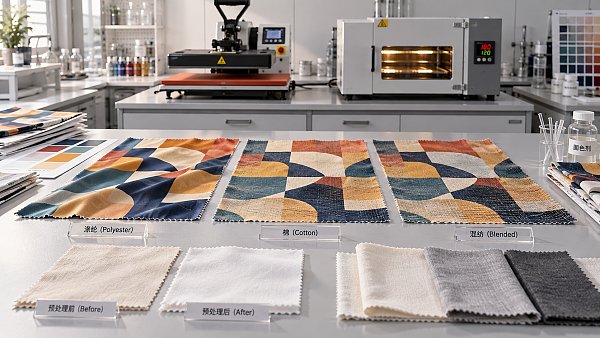
 Fabric LogicWater-Free Textile Printing: Fabric Compatibility and Pretreatment LimitsExplore water free textile printing for polyester, cotton, and blends. Learn pretreatment limits and key durability tests to choose the right process and avoid costly production mistakes.By: Chloe DuboisOct 26, 2026
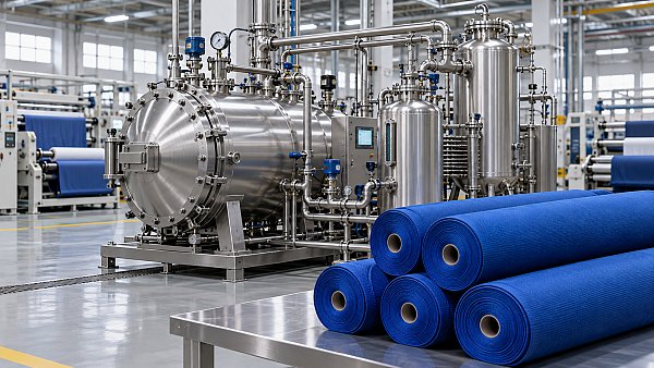
 Dyeing MachinesHow Waterless CO2 Dyeing Works—and Why Polyester Is a Strong FitDiscover how waterless dyeing with supercritical CO2 colors polyester, why this fiber is a strong fit, and what to verify for consistent shades and measurable resource savings.By: Chloe DuboisOct 26, 2026
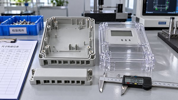
 Smart MetersSourcing Smart Meter Structural Components from China: An RFQ ChecklistExport smart meter structural components from China with confidence. Use this RFQ checklist to compare materials, tooling, quality, and delivered costs—and avoid costly sourcing mistakes.By: Dr. Elena VoltOct 26, 2026
 Optical SensorsEvaluating an Optical Detection Factory: Calibration and RepeatabilityEvaluate an optical detection factory with confidence. Learn how calibration, traceability, and repeatability trials reveal production reliability and help you choose the right supplier.By: Dr. Hideo TanakaOct 26, 2026
 Precision LensesChoosing a Welding Optics Supplier in China: Coatings and Damage ThresholdsCompare welding optics supplier China options for coating quality, verified damage thresholds, and batch consistency. Learn how to reduce downtime and buy with confidence.By: Dr. Hideo TanakaOct 26, 2026
 Aseptic FillingStainless Steel Mixing Tanks: Cleaning Access Checks Before PurchaseBuying stainless steel mixing tanks? Check cleaning access, CIP coverage, drainage, and acceptance tests before purchase to reduce changeover headaches and make a confident choice.By: Marcus SterlingOct 26, 2026
 Digital SeaRail Communication Bandwidth in Europe: GSM-R and FRMCS Bands ExplainedRail communication bandwidth Europe: explore GSM-R and FRMCS bands, compare 900 MHz and 1900 MHz spectrum, and discover key checks for smarter network planning.By: Captain Kenji SatoOct 26, 2026